This caught me out the other day and I had to find the answer deep within a Cisco document. To hopefully save someone else having to wade through all that, the commands to find out chassis serial numbers on the ASR9k are as follows:
RP/0/RSP0/CPU0:nodename#admin
Thu Sep 25 14:15:16.645 BST
RP/0/RSP0/CPU0:nodename(admin)#show dsc
Thu Sep 25 14:15:27.080 BST
---------------------------------------------------------
Node ( Seq) Role Serial State
---------------------------------------------------------
0/RSP0/CPU0 ( 0) ACTIVE ABC2345X678 PRIMARY-DSC
RP/0/RSP0/CPU0:nodename(admin)#
Err.... simple?
Thursday, 25 September 2014

Saturday, 13 September 2014
Crippling CPU Load on Back to Back ASAs
I was recently involved in troubleshooting a problem where an ASA firewall's
CPU was hitting 100%. One of its interfaces was seeing much higher traffic
levels than the others, so we did some fairly run-of-the-mill troubleshooting
including a packet capture. What this showed was the same, seemingly innocuous,
packet repeated thousands upon thousands of times.
The payload was identical, in fact everything from the IP layer and up remained identical from one frame to the next. The only thing that varied was that the source and destination MAC addresses were swapped each time - clearly the packet was ping-ponging between two devices.
We checked the MACs and found they were legitimate - one was the local firewall, while the other was its default gateway - another ASA upstream towards the Internet.
This got our attention. First of all there was a routing loop, which is bad enough, but a packet should never be able to loop forever like that. That's why we have Time To Live (TTL) after all - the number which decrements by one each time a packet goes through a routed hop with the packet being thrown away when its value reaches zero. The key thing here is that the packet, including its TTL, was not changing at all so it never got removed from the system.
The cause of the routing loop was relatively easily found by looking at the source and destination IPs on the packet. The setup was as follows:

What had happened here was that a RAS user had connected to the tenant firewall using their IPSec client and started talking to some devices on the server LAN:

At some point the IPSec session had ended while an internal device was still sending traffic towards the user. This creates an interesting corner case:
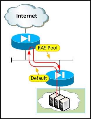
The routing is "correct" here - the multi-tenant firewall needs to route the RAS subnet via the tenant firewall so that RAS users can connect to shared resources. The tenant firewall needs to route the traffic outwards for it to hit the right crypto maps. The problem comes when a packet is destined for an IP in the RAS pool which is not associated with a live VPN session.
Our bodge to get us out of the immediate hole was to put a deny entry inbound on the mutli-tenant firewall for anything targeted at a RAS pool address. These packets should never make it onto the transit LAN as any legitimate traffic to that range would need to be tunneled via IPSec and therefore the multi-tenant firewall would see a public IP as the destination. After a lot of thinking we couldn't come up with a better answer than this and decided just to stop calling it a bodge.
OK, so first problem solved. Next question, why was the packet looping forever without ever reducing its TTL?
As it turns out this is by design on the ASA (and the good old fashioned PIX & FWSM before it). The idea is that if the firewall behaved like any other routed hop and decremented the TTL then it would be visible in traceroutes. To be fair if it did decrement TTL it would just appear as a black hole in the trace as the ASA doesn't really "do" unreachables unless you force its hand. This normally doesn't cause any problems, even if there is a routing loop. Take a typical deployment where an ASA is attached to a router as shown below:
 If we get a loop between the ASA and a traditional router then the packet
will eventually be taken out of the loop. Even though the ASA doesn't decrement
the TTL, the router does so it eventually gets dropped - half as fast as normal
and always by the router (which will punt the packet to the CPU and usually
generate an ICMP TTL expired, which can be pretty CPU intensive on small devices), but
it does get dropped eventually.
If we get a loop between the ASA and a traditional router then the packet
will eventually be taken out of the loop. Even though the ASA doesn't decrement
the TTL, the router does so it eventually gets dropped - half as fast as normal
and always by the router (which will punt the packet to the CPU and usually
generate an ICMP TTL expired, which can be pretty CPU intensive on small devices), but
it does get dropped eventually.
The problem comes when we have a pair of non-decrementing devices (ASAs) back to back at layer 2. Both devices route the packet but neither device decrements the TTL, so if there is a loop between the two it the packet will go around and around forever. Eugh...
The moral of the story is that it's probably best not to put ASAs back to back. I could have sworn I'd seen this setup in Cisco whitepapers before but, now that I look, I can't find it anywhere. The closest I can find is IOS firewall back to back with ASA or two ASAs with a server between. Perhaps there's a good reason for that :)
As with my situation, though, in most cases by the time you get to realise there is a problem the hardware has long since been bought, installed and is carrying live service. So what can you do?
Well, as noted above you can use ACLs to block potential loop traffic but in all honesty that just fixes by exception. You could be fairly liberal with what you block (e.g. drop all RFC 1918 addresses where you would expect to only see public IPs) but it's still imperfect.
A better idea would be to have at least one of the ASAs decrement TTL. It's a bit uncomfortable to retro-fit but there is a way built in to ASA versions 8.0(3) and above using "set connection decrement-ttl" under a policy map. There are two different ways to do it, one is to adjust the "global_policy" policy map which applies to the entire device by default, or you can create a new policy map to apply to a single interface.
Here's how to apply it to the entire device:
policy-map global_policy
class class-default
set connection decrement-ttl
!
The effect is immediate as the global_policy is applied to all traffic by default. Alternatively, if you only want to apply it to specific interfaces, you can create a separate policy map and apply it as follows:
policy-map asa_workaround
class inspection_default
inspect dns preset_dns_map
inspect ftp
inspect h323 h225
inspect h323 ras
inspect netbios
inspect rsh
inspect rtsp
inspect skinny
inspect esmtp
inspect sqlnet
inspect sunrpc
inspect tftp
inspect sip
inspect xdmcp
inspect icmp
class class-default
set connection decrement-ttl
!
service-policy asa_workaround interface interface-name
The above is modeled on the standard default policy & inspections, if you've changed yours from default you probably don't need to be reading this!
So there you have it - ASAs back to back is a bit dangerous unless you take measures to protect against routing loops. This can be in the form of strict ACLs or by enabling TTL decrement, either globally or on specific interfaces.
Cisco guide to enabling traceroute through ASA
Cisco guide to modular policy framework on ASA
The payload was identical, in fact everything from the IP layer and up remained identical from one frame to the next. The only thing that varied was that the source and destination MAC addresses were swapped each time - clearly the packet was ping-ponging between two devices.
We checked the MACs and found they were legitimate - one was the local firewall, while the other was its default gateway - another ASA upstream towards the Internet.
This got our attention. First of all there was a routing loop, which is bad enough, but a packet should never be able to loop forever like that. That's why we have Time To Live (TTL) after all - the number which decrements by one each time a packet goes through a routed hop with the packet being thrown away when its value reaches zero. The key thing here is that the packet, including its TTL, was not changing at all so it never got removed from the system.
The cause of the routing loop was relatively easily found by looking at the source and destination IPs on the packet. The setup was as follows:
What had happened here was that a RAS user had connected to the tenant firewall using their IPSec client and started talking to some devices on the server LAN:
At some point the IPSec session had ended while an internal device was still sending traffic towards the user. This creates an interesting corner case:

The routing is "correct" here - the multi-tenant firewall needs to route the RAS subnet via the tenant firewall so that RAS users can connect to shared resources. The tenant firewall needs to route the traffic outwards for it to hit the right crypto maps. The problem comes when a packet is destined for an IP in the RAS pool which is not associated with a live VPN session.
Our bodge to get us out of the immediate hole was to put a deny entry inbound on the mutli-tenant firewall for anything targeted at a RAS pool address. These packets should never make it onto the transit LAN as any legitimate traffic to that range would need to be tunneled via IPSec and therefore the multi-tenant firewall would see a public IP as the destination. After a lot of thinking we couldn't come up with a better answer than this and decided just to stop calling it a bodge.
OK, so first problem solved. Next question, why was the packet looping forever without ever reducing its TTL?
Root Cause
As it turns out this is by design on the ASA (and the good old fashioned PIX & FWSM before it). The idea is that if the firewall behaved like any other routed hop and decremented the TTL then it would be visible in traceroutes. To be fair if it did decrement TTL it would just appear as a black hole in the trace as the ASA doesn't really "do" unreachables unless you force its hand. This normally doesn't cause any problems, even if there is a routing loop. Take a typical deployment where an ASA is attached to a router as shown below:

The problem comes when we have a pair of non-decrementing devices (ASAs) back to back at layer 2. Both devices route the packet but neither device decrements the TTL, so if there is a loop between the two it the packet will go around and around forever. Eugh...
The moral of the story is that it's probably best not to put ASAs back to back. I could have sworn I'd seen this setup in Cisco whitepapers before but, now that I look, I can't find it anywhere. The closest I can find is IOS firewall back to back with ASA or two ASAs with a server between. Perhaps there's a good reason for that :)
As with my situation, though, in most cases by the time you get to realise there is a problem the hardware has long since been bought, installed and is carrying live service. So what can you do?
Well, as noted above you can use ACLs to block potential loop traffic but in all honesty that just fixes by exception. You could be fairly liberal with what you block (e.g. drop all RFC 1918 addresses where you would expect to only see public IPs) but it's still imperfect.
Making the ASA decrement TTL
A better idea would be to have at least one of the ASAs decrement TTL. It's a bit uncomfortable to retro-fit but there is a way built in to ASA versions 8.0(3) and above using "set connection decrement-ttl" under a policy map. There are two different ways to do it, one is to adjust the "global_policy" policy map which applies to the entire device by default, or you can create a new policy map to apply to a single interface.
Here's how to apply it to the entire device:
policy-map global_policy
class class-default
set connection decrement-ttl
!
The effect is immediate as the global_policy is applied to all traffic by default. Alternatively, if you only want to apply it to specific interfaces, you can create a separate policy map and apply it as follows:
policy-map asa_workaround
class inspection_default
inspect dns preset_dns_map
inspect ftp
inspect h323 h225
inspect h323 ras
inspect netbios
inspect rsh
inspect rtsp
inspect skinny
inspect esmtp
inspect sqlnet
inspect sunrpc
inspect tftp
inspect sip
inspect xdmcp
inspect icmp
class class-default
set connection decrement-ttl
!
service-policy asa_workaround interface interface-name
The above is modeled on the standard default policy & inspections, if you've changed yours from default you probably don't need to be reading this!
Summary
So there you have it - ASAs back to back is a bit dangerous unless you take measures to protect against routing loops. This can be in the form of strict ACLs or by enabling TTL decrement, either globally or on specific interfaces.
References
Cisco guide to enabling traceroute through ASA
Cisco guide to modular policy framework on ASA
Friday, 22 August 2014
AS-Override and the Importance of SoO
Recently I discovered that AS-override works in the opposite direction to what I thought! Now, this is largely academic as in most cases if you apply it to one peer you apply it everywhere, but I was dealing with a bit of a corner case and it caught me out as I had to mess about with (i.e. clear) a peer that I didn't really want to touch.
.gif)
.gif)
.gif)
Thankfully, as-override doesn't seem to be too fussy (unlike remove-private-as in earlier IOS) and will replace the ASN wherever it appears in the path. It literally operates like a "find and replace all". Here's the AS_PATH from the PE's perspective showing the customer's ASN, followed by the other carrier's ASN:
And here we see the route from CE2's perspective, with the 65000 (customer's) ASN replaced by the provider's ASN (100 shown in orange), followed by the untouched transit AS (in blue) and finally the provider's ASN is added on egress (in red):
Don't forget - the other carrier will also have to use as-override, otherwise CE1 will discard CE2's routes.
Now, as you'd imagine as-override works in conjunction with "local-as" on the PE. The happy news is that when local-as is in use, the ASN specified in the local-as command is used to override the customer ASN (after all, we're pretending to be that ASN). The bad news is you get some funny looking AS_PATHs.
Let's take a simple case where two CEs connect to a single PE, actually configured as AS 50 but masquerading as AS100:
.gif)
As you can see, on the PE, the route learned from CE1 shows the customer's ASN and also one copy of the pretend AS which is tacked on by default when using the local-as command:
If we look on CE2 we can see:
To explain this strange arrangement, we have:
Really, though, how many bodges do you want in play at once?
.gif)
.gif)
The withdrawals ripple through the network until CE2 is aware that the primary has gone away, decides to use the secondary and announces the route upstream. Seems legit so far...
.gif)
Cisco's config guides are a little bit ambiguous, saying:
"To configure a provider edge (PE) router to override the autonomous system number (ASN) of a site with the ASN of a provider, use the as-override command in VRF neighbor address family configuration mode. To restore the system to its default condition, use the no form of this command."
No mention whatsoever of in which direction the override happens. I always thought that a PE configured with AS override just didn't add the peer's AS to the AS_PATH when it received routes from the peer. It turns out I know nothing and that is not how it works at all.
In fact, as-override has no effect at all on received routes; it works only in the outbound direction. This makes sense, really, as the AS_PATH within carrier the carrier remains true (i.e. the service provider still gets to see what AS the routes originally came from). It's only when advertising routes out of the AS that as-override makes a difference, "overriding" the peer's ASN with the provider's.
But what does "overriding" mean? Let's take a look at some scenarios.
Simple Base Case
In a simple case where the AS_PATH (as seen by the provider) only contains a single entry and this corresponds with the peer's ASN, clearly the provider just replaces that with their own ASN. By "replace" I mean the peer's ASN is overwritten by the carrier's and then, as the route is advertised via eBGP, the carrier's ASN is added as normal. The route the peer receives, therefore, has an AS_PATH containing two copies of the carrier's ASN:
CE2#show ip bgp
BGP table version is 5, local router ID is 10.2.2.2
Status codes: s suppressed, d damped, h history, * valid, > best, i - internal,
              r RIB-failure, S Stale, m multipath, b backup-path, f RT-Filter,
              x best-external, a additional-path, c RIB-compressed,
Origin codes: i - IGP, e - EGP, ? - incomplete
RPKI validation codes: V valid, I invalid, N Not found

     Network          Next Hop            Metric LocPrf Weight Path
 *>  10.0.1.0/24      10.2.2.1                               0 100 100 i
 *>  10.0.2.0/24      0.0.0.0                  0         32768 i
CE2#
Prepended
So what if there are multiple copies of the peer's ASN at the start of the path? Well, as you might expect the whole topology doesn't suddenly tumble down. All copies of the peer ASN are replaced wih the carrier's ASN (after all, if we only replaced the first then the peer would still see it's own ASN and drop the update) before, again, adding the carrier's ASN as the route is advertised:
PE1#show ip bgp vpnv4 vrf cust1
BGP table version is 5, local router ID is 1.1.1.1
Status codes: s suppressed, d damped, h history, * valid, > best, i - internal,
              r RIB-failure, S Stale, m multipath, b backup-path, f RT-Filter,
              x best-external, a additional-path, c RIB-compressed,
Origin codes: i - IGP, e - EGP, ? - incomplete
RPKI validation codes: V valid, I invalid, N Not found

     Network          Next Hop            Metric LocPrf Weight Path
Route Distinguisher: 100:100 (default for vrf cust1)
 *>  10.0.1.0/24      10.1.1.2                 0             0 65000 65000 65000 i
 *>  10.0.2.0/24      10.2.2.2                 0             0 65000 i
PE1#
As observed on the PE, the route learned from CE1 has been prepended twice giving a total AS_PATH length of 3. All three of these 65000s will all be overridden when advertised towards CE2, creating the three 100s in orange and another copy of the local ASN (in red) will be added on egress as shown:
CE2#show ip bgp
BGP table version is 7, local router ID is 10.2.2.2
Status codes: s suppressed, d damped, h history, * valid, > best, i - internal,
              r RIB-failure, S Stale, m multipath, b backup-path, f RT-Filter,
              x best-external, a additional-path, c RIB-compressed,
Origin codes: i - IGP, e - EGP, ? - incomplete
RPKI validation codes: V valid, I invalid, N Not found

     Network          Next Hop            Metric LocPrf Weight Path
 *>  10.0.1.0/24      10.2.2.1                               0 100 100 100 100 i
 *>  10.0.2.0/24      0.0.0.0                  0         32768 i
CE2#
ASN Arbitrarily Contained in the AS_PATH
Another possibility exists where there are multiple AS involved. What if the customer connects to two different carriers who, in turn, connect to each other? This introduces the possibility that a customer route is learned from the other carrier, which then needs to be advertised out to the customer. The diagram below probably explains things better:
Thankfully, as-override doesn't seem to be too fussy (unlike remove-private-as in earlier IOS) and will replace the ASN wherever it appears in the path. It literally operates like a "find and replace all". Here's the AS_PATH from the PE's perspective showing the customer's ASN, followed by the other carrier's ASN:
PE1#show ip bgp vpnv4 vrf cust1
BGP table version is 6, local router ID is 1.1.1.1
Status codes: s suppressed, d damped, h history, * valid, > best, i - internal,
              r RIB-failure, S Stale, m multipath, b backup-path, f RT-Filter,
              x best-external, a additional-path, c RIB-compressed,
Origin codes: i - IGP, e - EGP, ? - incomplete
RPKI validation codes: V valid, I invalid, N Not found

     Network          Next Hop            Metric LocPrf Weight Path
Route Distinguisher: 100:100 (default for vrf cust1)
 *>  192.168.0.0      172.16.1.2                             0 200 65000 i
PE1#
And here we see the route from CE2's perspective, with the 65000 (customer's) ASN replaced by the provider's ASN (100 shown in orange), followed by the untouched transit AS (in blue) and finally the provider's ASN is added on egress (in red):
CE2#show ip bgp
BGP table version is 4, local router ID is 10.2.2.2
Status codes: s suppressed, d damped, h history, * valid, > best, i - internal,
              r RIB-failure, S Stale, m multipath, b backup-path, f RT-Filter,
              x best-external, a additional-path, c RIB-compressed,
Origin codes: i - IGP, e - EGP, ? - incomplete
RPKI validation codes: V valid, I invalid, N Not found

     Network          Next Hop            Metric LocPrf Weight Path
 *>  192.168.0.0      10.2.2.1                               0 100 200 100 i
CE2#
Don't forget - the other carrier will also have to use as-override, otherwise CE1 will discard CE2's routes.
In Coordination with "local-as"
Now, as you'd imagine as-override works in conjunction with "local-as" on the PE. The happy news is that when local-as is in use, the ASN specified in the local-as command is used to override the customer ASN (after all, we're pretending to be that ASN). The bad news is you get some funny looking AS_PATHs.
Let's take a simple case where two CEs connect to a single PE, actually configured as AS 50 but masquerading as AS100:
As you can see, on the PE, the route learned from CE1 shows the customer's ASN and also one copy of the pretend AS which is tacked on by default when using the local-as command:
PE#show ip bgp vpnv4 vrf cust1
BGP table version is 4, local router ID is 1.1.1.1
Status codes: s suppressed, d damped, h history, * valid, > best, i - internal,
              r RIB-failure, S Stale, m multipath, b backup-path, f RT-Filter,
              x best-external, a additional-path, c RIB-compressed,
Origin codes: i - IGP, e - EGP, ? - incomplete
RPKI validation codes: V valid, I invalid, N Not found

     Network          Next Hop            Metric LocPrf Weight Path
Route Distinguisher: 100:100 (default for vrf cust1)
 *>  10.10.10.0/24    10.1.1.2                 0             0 100 65000 i
PE#
If we look on CE2 we can see:
CE2#show ip bgp
BGP table version is 33, local router ID is 192.168.2.2
Status codes: s suppressed, d damped, h history, * valid, > best, i - internal,
              r RIB-failure, S Stale, m multipath, b backup-path, f RT-Filter,
              x best-external, a additional-path, c RIB-compressed,
Origin codes: i - IGP, e - EGP, ? - incomplete
RPKI validation codes: V valid, I invalid, N Not found

     Network          Next Hop            Metric LocPrf Weight Path
 *>  10.10.10.0/24    10.2.2.1                               0 100 50 100 100 i
CE2#
To explain this strange arrangement, we have:
- 100 - the pretend ASN (normal local-as behaviour, added on egress)
- 50 - the real ASN (normal local-as behaviour, added on egress)
- 100 - the pretend ASN (normal local-as behaviour, added on ingress from CE1)
- 100 - the pretend ASN used in place of the customer ASN (as-override)
Really, though, how many bodges do you want in play at once?
The Importance of SoO
Whenever altering the behaviour of something as important as BGP's loop prevention mechanism it is important to have a safety net. Unless you're very careful it's possible to introduce routing loops, particularly where multiple ISPs / ASNs are involved. Site of Origin, or SoO for short, provides just such a safety net.
The mode of operation is as follows:
The mode of operation is as follows:
- A SoO extended community is allocated for each customer site
- The SoO value is configured against each customer BGP peer within the PE router
- As routes are learned from a neighbour, the SoO extended community is attached to them to indicate their site of origin
- The PE checks any routes that are waiting to be advertised to a BGP peer and handles them according to the following rules:
- Any routes that are found to have the same SoO as the peer are not advertised to that particular peer
- Any routes that have a SoO community different to the peer's are advertised to that peer
- Any routes that do not have a SoO community attached are advertised
Now, SoO is occasionally overlooked as as-override often appears to work without it. Really, though, you are storing up problems for later.
Here's an example of SoO config on the PE:
router bgp 100
!
address-family ipv4 vrf cust1
neighbor 10.1.1.2 remote-as 65000
neighbor 10.1.1.2 activate
neighbor 10.1.1.2 as-override
neighbor 10.1.1.2 soo 100:1
neighbor 10.2.2.2 remote-as 65000
neighbor 10.2.2.2 activate
neighbor 10.2.2.2 as-override
neighbor 10.2.2.2 soo 100:2
exit-address-family
If there were two links into the same site (or into two sites joined by a backdoor network) then we would set the same SoO on both of its links. Since it uses an extended community (and this is a VRF so extended communities must be turned on) the SoO principle works across sites as well. It's important that different sites use different SoO values, otherwise they will not be able to learn each other's routes.
There's one minor, almost cosmetic, quirk you get if you enable as-override without SoO:
If two CEs attach to the same PE then they will receive a copy of their own routes back from the PE.
Here's an example of SoO config on the PE:
router bgp 100
!
address-family ipv4 vrf cust1
neighbor 10.1.1.2 remote-as 65000
neighbor 10.1.1.2 activate
neighbor 10.1.1.2 as-override
neighbor 10.1.1.2 soo 100:1
neighbor 10.2.2.2 remote-as 65000
neighbor 10.2.2.2 activate
neighbor 10.2.2.2 as-override
neighbor 10.2.2.2 soo 100:2
exit-address-family
If there were two links into the same site (or into two sites joined by a backdoor network) then we would set the same SoO on both of its links. Since it uses an extended community (and this is a VRF so extended communities must be turned on) the SoO principle works across sites as well. It's important that different sites use different SoO values, otherwise they will not be able to learn each other's routes.
Problems Without SoO
There's one minor, almost cosmetic, quirk you get if you enable as-override without SoO:
If two CEs attach to the same PE then they will receive a copy of their own routes back from the PE.
This is a strange side-effect of the way update-groups work. Normally the PE would receive routes from both CEs, put together a list of updates and send them to both CEs - at this point each CE would see its own updates but would weed them out due to the AS_PATH containing the local ASN. With as-override enabled on the PE, the customer ASN is overridden with the provider's and the CE has no way to tell that the route was just echoed back.
Normally this doesn't matter as other mechanisms cause the locally injected route to be preferred (weight is set to 32768 for locally originated prefixes unless overridden, static routes generally have a better AD, etc) so it just looks a bit weird. There are cases where this does cause (rather drastic) problems, though. Take the following, not too far-fetched situation:
Normally this doesn't matter as other mechanisms cause the locally injected route to be preferred (weight is set to 32768 for locally originated prefixes unless overridden, static routes generally have a better AD, etc) so it just looks a bit weird. There are cases where this does cause (rather drastic) problems, though. Take the following, not too far-fetched situation:
When the primary feed is up everything is great. The local preference of routes learned over the secondary feed is set to 50 by a route-map to ensure that they are less preferable than those received from the primary.
Let's break the primary feed and see what happens:
The withdrawals ripple through the network until CE2 is aware that the primary has gone away, decides to use the secondary and announces the route upstream. Seems legit so far...
Ah, no... this doesn't look right. The PE has echoed the route back to CE2 and, since the echoed route doesn't contain the local ASN and has a default local-preference of 100 it is now CE2's favourite.
.gif)
Now we're in a right knot. CE2 has told the PE that it has a new route to use, but it contains the carrier ASN in the AS_PATH. The PE drops that as a loop, removes the route from its BGP table and sends a withdrawal message to CE2.
We are effectively back to the start where CE2 only has one option - it will take the route it is learning over the secondary feed and advertise it to the PE. Round and around we go...
There are a few tell-tale signs that this is happening. First of all there will be intermittent connectivity (usually in 30 second steps):
CE2#ping 10.10.10.1 repeat 1000
Type escape sequence to abort.
Sending 1000, 100-byte ICMP Echos to 10.0.1.1, timeout is 2 seconds:
!!!!!!!!!!!!!!!!!!!!!!!!!!!!!!!!!!!!!!!!!!!!!!!!!!!!!!!!!!!!!!!!!!!!!!
!!!!!!!!!!!!!!!!!!!!!!!!!!!!!!!!!!!!!!!!!!!!!!................!!!!!!!!
!!!!!!!!!!!!!!!!!!!!
The next big giveaway is that when you run "show ip route" the age of the affected route(s) is always very low, typically under 30 seconds on standard BGP timers, and the path alternates between the same two next hops over and over:
CE2#show ip route 10.10.10.0
Routing entry for 10.10.10.0/24
  Known via "bgp 65000", distance 20, metric 0
  Tag 100, type external
  Last update from 10.2.2.1 00:00:29 ago
  Routing Descriptor Blocks:
  * 10.2.2.1, from 10.2.2.1, 00:00:29 ago
      Route metric is 0, traffic share count is 1
      AS Hops 3
      Route tag 100
      MPLS label: none
CE2#show ip route 10.10.10.0
Routing entry for 10.10.10.0/24
  Known via "bgp 65000", distance 20, metric 0
  Tag 200, type external
  Last update from 192.168.2.1 00:00:02 ago
  Routing Descriptor Blocks:
  * 192.168.2.1, from 192.168.2.1, 00:00:02 ago
      Route metric is 0, traffic share count is 1
      AS Hops 1
      Route tag 200
      MPLS label: none
CE2#
Finally, another good indication is that your BGP table version number is through the roof and continuously incrementing:
CE2#sh ip bgp
BGP table version is 51423, local router ID is 192.168.2.2
Status codes: s suppressed, d damped, h history, * valid, > best, i - internal,
              r RIB-failure, S Stale, m multipath, b backup-path, f RT-Filter,
              x best-external, a additional-path, c RIB-compressed,
Origin codes: i - IGP, e - EGP, ? - incomplete
RPKI validation codes: V valid, I invalid, N Not found

     Network          Next Hop            Metric LocPrf Weight Path
 *>  10.10.10.0/24    10.2.2.1                               0 100 100 200 i
 *                    192.168.2.1              0     50      0 200 i

CE2#
Note that you can also see the genuine and echoed routes in the BGP table (sometimes, re-check periodically).
It's possible to bodge together a route-map or prefix-list to 'fix' this, in fact just applying any unique route-map outbound on the PE will put the peer into a separate update-group which will bodge it into action. Please just use SoO, though - that's what it's there for!
Monday, 21 April 2014
Weird 2960 ARP issue
I've been doing a load of migrations lately which involve moving circuits from one head end PE to another and I've consistently run into a problem with 2960 switches running the LAN base image. Basically, following the moves I consistently find that although everything attached to the switch is still reachable, I lose management connectivity to the on-site switch at the far end of the circuit. Strangely it is always possible to ping / SSH to the switch from the connected interface but not from the management station.
Protocol Address Age (min) Hardware Addr Type Interface
Internet 192.168.50.50 167 00c0.321a.be00 ARPA Vlan120
Internet 10.123.145.193 0 189c.5dfe.be1f ARPA Vlan120
Internet 10.123.145.194 - 3037.ade1.a4b4 ARPA Vlan120
The issue seems to be down to some really weird behaviour with the ARP table of the 2960. LAN base is a layer 2 only image so the box can only have one SVI active and relies on a default gateway to get to any other networks - nothing new there. The weird thing is that for some reason when the 2960 wants to send traffic to a remote network, for example responding to a ping from a management station, it creates an ARP entry in its table for the remote IP with the gateway's MAC.
Remote-Sw-01#show ip arpProtocol Address Age (min) Hardware Addr Type Interface
Internet 192.168.50.50 167 00c0.321a.be00 ARPA Vlan120
Internet 10.123.145.193 0 189c.5dfe.be1f ARPA Vlan120
Internet 10.123.145.194 - 3037.ade1.a4b4 ARPA Vlan120
This seems to happen irrespective of whether proxy arp is enabled on the upstream interface, plus in any case the switch should not be ARPing for anything outside its subnet, so I seriously doubt that the entry is being built by any genuine ARP transaction. Looks like a bodge to me :)
Once these spurious non-adjacent ARP entries are in place they do not seem to get overwritten by, for example, receiving traffic from a given IP with a different MAC. Fortunately, legitimate entries for the local subnet do get overwritten, which leaves the door slightly ajar.
I can't see any way to stop the annoying behaviour, so the obvious workaround is to SSH in from the connected interface (check your ACLs!) or and blow any entries still referring to the old gateway MAC out of the ARP table.
Remote-Sw-01#clear ip arp 192.168.50.50
Remote-Sw-01#show ip arp
Protocol Address Age (min) Hardware Addr Type Interface
Internet 192.168.50.50 0 189c.5dfe.be1f ARPA Vlan120
Internet 10.123.145.193 1 189c.5dfe.be1f ARPA Vlan120
Internet 10.123.145.194 - 3037.ade1.a4b4 ARPA Vlan120
Remote-Sw-01#show ip arp
Protocol Address Age (min) Hardware Addr Type Interface
Internet 192.168.50.50 0 189c.5dfe.be1f ARPA Vlan120
Internet 10.123.145.193 1 189c.5dfe.be1f ARPA Vlan120
Internet 10.123.145.194 - 3037.ade1.a4b4 ARPA Vlan120
At that point the correct gateway MAC will be learned and connectivity should instantly be restored. Another alternative is to SSH from a second management station which hasn't connected recently enough to have an ARP entry. Of course, if you have 4 hours you could just wait for the ARP entry to expire.
Wednesday, 9 April 2014
Weird Problem Running Password Recovery on a PIX 501
Today I dug out an old PIX 501 from the store room to do some testing (don't ask). As expected, it already had a config including some unknown enable password so I was forced to perform a password recovery on it. I've done a million of these on routers and switches but probably only once or twice on a PIX so I wound up on Cisco's how to password recover a PIX page giving myself a quick refresher on how to do it.
The password recovery process on a PIX is version dependent, requiring the right recovery image for the installed PIX software. Fortunately for me the console was not set with a password so I could use "show ver" what was running on the box:
VPN-TEST> show ver
Cisco PIX Firewall Version 6.3(5)
Cisco PIX Device Manager Version 3.0(4)
Compiled on Thu 04-Aug-05 21:40 by morlee
<snip>
"Great", I thought, and downloaded the 6.3 recovery image. The process itself is pretty straightforward and explained on the Cisco instruction page so I won't go over it in detail. After breaking the boot sequence and firing up the TFTP I was greeted with this:
monitor> tftp
tftp 8529-np63.bin@10.10.10.1.....................................................................................................................................................................................
Received 92160 bytes
Cisco Secure PIX Firewall password tool (3.0) #0: Thu Jul 17 08:01:09 PDT 2003
Flash=E28F640J3 @ 0x3000000
BIOS Flash=E28F640J3 @ 0xD8000
Do you wish to erase the passwords? [yn]
Of course I pressed "y", only to be told:
▒o passwords or aaa commands were found.
Rebooting....
How rude! Following that I returned to trying the default cisco / pix / blank passwords, in case I'd fat-fingered them earlier, but nothing worked. There *was* a password there, dammit!
After a fair bit of searching I soon realised that this was not a common problem. There were only a couple of forum posts quoting the "no passwords or aaa commands were found" message and none of them had a solution.
Out of desperation, as much as anything, I tried the PIX 7/8 recovery image:
monitor> tftp
tftp 8529-np70.bin@10.10.10.1.............................................................................................................................................................................................................................................................
Received 129024 bytes
Cisco PIX Security Appliance password tool (3.0) #0: Thu Jun 9 21:45:44 PDT 2005
This utility is not supported on this platform
Rebooting....
Huff. OK, last try. Let's go with the next version down - 6.2 and see if that works:
monitor> tftp
tftp 8529-np62.bin@10.10.10.1.................................................................................................................................................
Received 73728 bytes
Cisco Secure PIX Firewall password tool (3.0) #0: Wed Mar 27 11:02:16 PST 2002
Flash=E28F640J3 @ 0x3000000
BIOS Flash=E28F640J3 @ 0xD8000
Do you wish to erase the passwords? [yn]
Well, at least it ran this time. Naturally I typed "y":
The following lines will be removed from the configuration:
enable password XJEP6/bAhsOZPahK encrypted
passwd 2KFQnbNIdI.2KYOU encrypted
Do you want to remove the commands listed above from the configuration? [yn]
Ah, the good old default "cisco" passwd entry (who can forget the "KYOU" on the end?) along with the troublesome unknown enable password. I've mangled it to avoid leaking genuine information. After pressing "y" I got the following promising message:
Passwords and aaa commands have been erased.
Rebooting....
This time it actually worked, restoring the enable password to blank!
Out of curiosity I thought I'd check whether the config file was last saved under PIX 6.2 (a long shot, admittedly):
LAB-501# show run
: Saved
:
PIX Version 6.3(5)
<snip>
Er, nope. I can only assume that this little runt of a firewall had previously run 6.2 code and had later been upgraded. I vaguely remember upgrading PIXes in the past and being warned about scary, irreversible changes being made to the flash filesystem - perhaps the file system is a little different between 6.2 and 6.3, but it doesn't bother to overwrite the flash for upgrades between minor releases? Either way, the 6.3 recovery image evidently didn't understand it and 6.2 did.
So there you have it. I suppose in theory you could just start high and work backwards until it succeeds. I've grabbed every recovery image on the page while they're still available - I don't expect Cisco to take them down (they are over a decade old now and still up) but you never know.
There you go. Now there is an answer for the 1 other person in the world who may ever have the same problem trying to revive a completely defunct model of firewall. Long live the PIX!
The password recovery process on a PIX is version dependent, requiring the right recovery image for the installed PIX software. Fortunately for me the console was not set with a password so I could use "show ver" what was running on the box:
VPN-TEST> show ver
Cisco PIX Firewall Version 6.3(5)
Cisco PIX Device Manager Version 3.0(4)
Compiled on Thu 04-Aug-05 21:40 by morlee
<snip>
"Great", I thought, and downloaded the 6.3 recovery image. The process itself is pretty straightforward and explained on the Cisco instruction page so I won't go over it in detail. After breaking the boot sequence and firing up the TFTP I was greeted with this:
monitor> tftp
tftp 8529-np63.bin@10.10.10.1.....................................................................................................................................................................................
Received 92160 bytes
Cisco Secure PIX Firewall password tool (3.0) #0: Thu Jul 17 08:01:09 PDT 2003
Flash=E28F640J3 @ 0x3000000
BIOS Flash=E28F640J3 @ 0xD8000
Do you wish to erase the passwords? [yn]
Of course I pressed "y", only to be told:
▒o passwords or aaa commands were found.
Rebooting....
How rude! Following that I returned to trying the default cisco / pix / blank passwords, in case I'd fat-fingered them earlier, but nothing worked. There *was* a password there, dammit!
After a fair bit of searching I soon realised that this was not a common problem. There were only a couple of forum posts quoting the "no passwords or aaa commands were found" message and none of them had a solution.
Out of desperation, as much as anything, I tried the PIX 7/8 recovery image:
monitor> tftp
tftp 8529-np70.bin@10.10.10.1.............................................................................................................................................................................................................................................................
Received 129024 bytes
Cisco PIX Security Appliance password tool (3.0) #0: Thu Jun 9 21:45:44 PDT 2005
This utility is not supported on this platform
Rebooting....
Huff. OK, last try. Let's go with the next version down - 6.2 and see if that works:
monitor> tftp
tftp 8529-np62.bin@10.10.10.1.................................................................................................................................................
Received 73728 bytes
Cisco Secure PIX Firewall password tool (3.0) #0: Wed Mar 27 11:02:16 PST 2002
Flash=E28F640J3 @ 0x3000000
BIOS Flash=E28F640J3 @ 0xD8000
Do you wish to erase the passwords? [yn]
Well, at least it ran this time. Naturally I typed "y":
The following lines will be removed from the configuration:
enable password XJEP6/bAhsOZPahK encrypted
passwd 2KFQnbNIdI.2KYOU encrypted
Do you want to remove the commands listed above from the configuration? [yn]
Ah, the good old default "cisco" passwd entry (who can forget the "KYOU" on the end?) along with the troublesome unknown enable password. I've mangled it to avoid leaking genuine information. After pressing "y" I got the following promising message:
Passwords and aaa commands have been erased.
Rebooting....
This time it actually worked, restoring the enable password to blank!
Out of curiosity I thought I'd check whether the config file was last saved under PIX 6.2 (a long shot, admittedly):
LAB-501# show run
: Saved
:
PIX Version 6.3(5)
<snip>
Er, nope. I can only assume that this little runt of a firewall had previously run 6.2 code and had later been upgraded. I vaguely remember upgrading PIXes in the past and being warned about scary, irreversible changes being made to the flash filesystem - perhaps the file system is a little different between 6.2 and 6.3, but it doesn't bother to overwrite the flash for upgrades between minor releases? Either way, the 6.3 recovery image evidently didn't understand it and 6.2 did.
So there you have it. I suppose in theory you could just start high and work backwards until it succeeds. I've grabbed every recovery image on the page while they're still available - I don't expect Cisco to take them down (they are over a decade old now and still up) but you never know.
There you go. Now there is an answer for the 1 other person in the world who may ever have the same problem trying to revive a completely defunct model of firewall. Long live the PIX!
Wednesday, 2 April 2014
Bending the MPLS Security Model - part 2 (Foundations)
The Foundations of MPLS Tomfoolery
In the previous post I briefly reviewed the constructs of MPLS services and how traffic is segregated. The key takeaways from that post are that:- Label switch routers generally only interpret / act on the outer label
- Basically all the security is provided / enforced through the control plane which restricts reachability by selectively advertising service labels
- Routing for VRFs is different from normal IP due to the use of route distinguishers and route targets
All the intelligence in an MPLS network sits around the edge. It was designed this way so that the devices in the middle could dumbly (quickly) pass frames on, swapping one label for another without needing any knowledge of what the traffic is or how it should route. The core (P) nodes do not need to know anything about VRFs, IPv6 or even BGP - the edge PEs do all the protocol work, keep track of how that translates into labels and just hand labelled traffic into the core to be switched across to another node which understands.
Essentially the only security feature of the data plane is to drop frames with unknown labels. While you wouldn't expect to see it in the steady state, during many different types of legitimate convergence event frames can arrive with invalid labels attached. Generally this will only happen for milliseconds at a time but with high speed traffic flows or momentary loops that can mean a lot of frames. Mostly for this reason, I suppose, I've never seen a platform that logs or traps in the event of receiving an invalid label. This is helpful as it allows us to guess at labels without creating ridiculous amounts of noise.
Another
less-thought-about aspect of (frame mode) MPLS is that the label space
is platform wide, in other words it doesn't matter which interface
receives a packet, only what the top label is. So no real sanity
checking, and certainly no RPF checks (labels only indicate destination,
not source) - frames can arrive from any angle and be treated the same.
All in all we
have a system where all the decisions are made by the ingress PE. When a
"customer" packet needs to be routed by the PE, it does a lookup to
decide what service label is required (to indicate the correct VPN or
pseudowire the egress PE) and what transport label should be applied (to
indicate that the core should pass the traffic to the correct egress
PE). Since nothing gets checked along the way, any device can send
traffic to any service on any PE if the right labels are
applied.
Label IDs are 20 bits wide, which would be a fair old area for an attacker to 'spray and pray'. Luckily for the attacker, though, the dynamic label assignment algorithms of various platforms are pretty predictable (in fact, they're usually sequential). The attacker is also helped by the fact that packets with invalid labels are silently dropped, leaving little in the way of evidence that anyone has been "poking around".
The default dynamic assignment label ranges for a few common platforms are:
Cisco (IOS / IOS-XE): 16 upwards
Cisco IOS-XR: 16000 upwards
Juniper Junos: 100000 upwards
Alcatel 7750: 131071 downwards
Most kit will fall into one of these categories, so even if you don't know what kit is in use you still have a good chance of hitting the right labels.
A few relatively straightforward attacks spring to mind, each of which will be covered in separate blog posts. The scenarios are:
- How to inject packets into a layer 2 EoMPLS pipe
- How to trombone / MITM layer 3 VPN traffic
- How to go after the PEs themselves
Stay tuned!
Monday, 17 March 2014
Bending the MPLS Security Model part 1 (introduction)
A lot of people think MPLS is quite a secure technology - perhaps it's all the talk of VPNs or the fact that various government security standards permit the use of VRFs to segregate data at different security levels while VLANs are not considered secure enough. I've always thought that was a bit strange, because fundamentally when on the wire VLANs and MPLS both use a 4 byte tag to determine what can talk to what.
In this mini-series of blog posts I will briefly go through the building blocks of layer 2 and layer 3 MPLS VPNs, the controls these provide and a few gotchas before finally exploring some ways to use and abuse the mechanisms to cause mischief on the network.
Labelled traffic can be queued / scheduled at the interface for QoS purposes but once traffic is labelled there's very little that can be done with regards to manipulation. ACLs can't be applied to filter labelled traffic and, since there is no "source" field in an MPLS header, uRPF checking is not possible.
The whole security model of MPLS is premised on the fact that traffic cannot pass without the right labels and route / label learning is restricted by the control plane. For anyone not familiar with MPLS VPNs, I'll provide a very high-level introduction to how this happens in practice.
Separation is achieved by basically bolting the RD onto the beginning of every IP prefix known within the VRF. So for instance, if VRF "A" uses RD 100:100, when it learns a route to 10.10.10.0/24 that will be known internally as 100:100:10.10.10.0/24. If an identical prefix is learned in VRF "B" with an RD of 200:200, that will be known internally as 200:200:10.10.10.0/24. Since the extended versions of the two prefixes are different, there is no conflict and both can be used independently.
Layer 3 MPLS VPNs use MP-BGP to share routing information between devices. MP-BGP works with the extended prefixes described above and any VPN route that will be advertised to other devices must have a route target community attached (defined as an export route target for the VRF). That route can only be learned by another VRF, either locally or remotely, which is configured to import routes with that target.
In simple VPNs the import and export route targets match, meaning that every member VRF learns the routes that are present in every other member VRF. This produces a basic any-any connectivity model.
Clearly, since each VRF learns routes from every other VRF there is a full mesh of connectivity.
The import and export can be controlled independently, so a variety of topologies can be created quite simply. For example, to create a hub and spoke setup, simply configure the hub to export the hub route target while importing the spoke route target and configure the spokes to export the spoke route target while importing the hub route target.
Spokes do not learn from each other because they only import routes with the hub target. Without knowledge of each other's routes, no traffic can pass between the spoke VRFs.
Another common application of multiple route targets is in setting up "grey management" VRFs - that is a single VRF containing centralised management platforms which are used for operational support and maintenance of devices in multiple customer VRFs.
The grey management routes are leaked into each customer's VRF, providing reachability to the NMS. The management VRF in turn imports each customer VRF's routes to provide reachability to the managed CPEs. Typically the managed CPEs will each have a loopback address assigned from a known range and the management VRF will have an import filter allowing only the routes to those loopbacks to be imported. Public address space is usually used to avoid any addressing conflicts within the customer VRFs.
One big mistake that can easily be made is for the spoke to accidentally advertise a summary or default route. The diagram below shows what happens in this case:
The spokes still cannot learn each others' routes, however they do learn the default route from the hub. If PC B tries to send traffic to PC C's IP address, the traffic will follow the default route towards the hub. The hub knows all the spoke routes and so sends the traffic onwards towards PC C. So despite VRF B not containing any routes from VRF C and vice-versa, traffic can still flow between them.
The workaround: don't summarise or default route within overlapping or partial mesh VRFs, particularly at hub sites.


Since the necessary service labels are signalled directly between the two interested PEs, they are not known elsewhere in the network and no other devices can participate in the pseudowire, i.e. it is point-to-point.
In this mini-series of blog posts I will briefly go through the building blocks of layer 2 and layer 3 MPLS VPNs, the controls these provide and a few gotchas before finally exploring some ways to use and abuse the mechanisms to cause mischief on the network.
Introduction to the MPLS Security Model
In addition to its unrivaled flexibility and scalability, the most significant benefit of MPLS is its very simple (and therefore fast) data plane:- As frame enter at the MPLS edge, the PE adds (pushes / imposes) labels to the frame header.
- At each hop inside the MPLS core a simple table lookup is done on the outer label number. The lookup returns a replacement label, outgoing interface and encap to be written onto the outgoing frame (a label swap).
- As frames reach the edge of the MPLS core, the PE removes (pops) the outer label and acts on (i.e. routes, switches or processes) whatever it finds inside.
Labelled traffic can be queued / scheduled at the interface for QoS purposes but once traffic is labelled there's very little that can be done with regards to manipulation. ACLs can't be applied to filter labelled traffic and, since there is no "source" field in an MPLS header, uRPF checking is not possible.
The whole security model of MPLS is premised on the fact that traffic cannot pass without the right labels and route / label learning is restricted by the control plane. For anyone not familiar with MPLS VPNs, I'll provide a very high-level introduction to how this happens in practice.
Layer 3 VPNs
In order to maintain several, possibly overlapping, routing tables, an MPLS router uses the concept of VRFs. A VRF is a distinct routing instance, a bit like a virtual router, with its own interfaces, routing table and routing protocols. Internally the MPLS router uses a route distinguisher, or RD, to keep one VRF's routes separate from another's.Separation is achieved by basically bolting the RD onto the beginning of every IP prefix known within the VRF. So for instance, if VRF "A" uses RD 100:100, when it learns a route to 10.10.10.0/24 that will be known internally as 100:100:10.10.10.0/24. If an identical prefix is learned in VRF "B" with an RD of 200:200, that will be known internally as 200:200:10.10.10.0/24. Since the extended versions of the two prefixes are different, there is no conflict and both can be used independently.
Layer 3 MPLS VPNs use MP-BGP to share routing information between devices. MP-BGP works with the extended prefixes described above and any VPN route that will be advertised to other devices must have a route target community attached (defined as an export route target for the VRF). That route can only be learned by another VRF, either locally or remotely, which is configured to import routes with that target.
In simple VPNs the import and export route targets match, meaning that every member VRF learns the routes that are present in every other member VRF. This produces a basic any-any connectivity model.
 |
| Any-Any VRF Topology |
Clearly, since each VRF learns routes from every other VRF there is a full mesh of connectivity.
The import and export can be controlled independently, so a variety of topologies can be created quite simply. For example, to create a hub and spoke setup, simply configure the hub to export the hub route target while importing the spoke route target and configure the spokes to export the spoke route target while importing the hub route target.
 |
| Hub and Spoke VRF Topology |
Another common application of multiple route targets is in setting up "grey management" VRFs - that is a single VRF containing centralised management platforms which are used for operational support and maintenance of devices in multiple customer VRFs.
 |
| Grey Management VRF Topology |
Gotchas
In both the hub-and-spoke and grey management scenarios there is a centralised point which has all the routing information and can communicate with everything, while the peripheral VRFs only learn a reduced set of routes and therefore can only communicate with the networks within their limited view. Spokes do not import the spoke route-target and therefore cannot "see" each other. Customer VRFs do not import each others' route targets and so separation is maintained.One big mistake that can easily be made is for the spoke to accidentally advertise a summary or default route. The diagram below shows what happens in this case:
 |
| Hub and Spoke Topology Broken by Default Route |
The workaround: don't summarise or default route within overlapping or partial mesh VRFs, particularly at hub sites.
Layer 2 VPNs (Pseudowires)
MPLS pseudowires are essentially point-to-point tunnels that transport layer 2 frames using MPLS transport. A pseudowire simply takes a frame in one end and moves it, as is, to the other end. Pseudowires are typically signalled using targeted LDP - that is a Link Distribution Protocol connection directly between the PEs on each end of the pseudowire. The two endpoints communicate directly with each other to signal the labels to be used for a particular pseudowire, as differentiated by a virtual circuit identifier (VCID).Since the necessary service labels are signalled directly between the two interested PEs, they are not known elsewhere in the network and no other devices can participate in the pseudowire, i.e. it is point-to-point.
Gotchas
Due to the simple nature of pseudowires, the gotchas are pretty minor. Provided the two peers are configured with matching VC IDs, most problems are going to be down to "schoolboy errors":
- Mismatched VC IDs
- Mismatched VC types (VLAN vs. Ethernet)
- Broken label-switched path between peers
- TLDP session unable to come up (control plane filters, mismatched LDP keys)
- Mismatched MTU (each vendor seems to count in a different way)
- Port MTU smaller than the configured VC MTU
Summary
This post really only reviewed at a very high level how MPLS VPNs are set up and how one is kept distinct from another. In the next post I will start to look at some weaknesses and opportunities for mischief.
Subscribe to:
Posts (Atom)